Modelling the scenario
The scenario
We want entrants to improve speech in the presence of background noise; see Figure 1. On the left there is a person with a quantified hearing loss who is listening to speech from the target talker on the right. Both people are in a living room. There is interfering noise from a number of sources (a TV and washing machine in this case). The speech and noise are sensed by microphones on the hearing aids of the listener. The task is to take these microphone feeds and the listener’s hearing characteristics, and produce signals for the hearing aid processor that will make the speech more intelligible. We will evaluate the success of the processing using a combination of objective metrics for speech intelligibility and quality.

Baseline system and software tools
Challenge entrants are supplied with an end-to-end baseline system. Figure 2 shows a simplified schematic, which comprises:
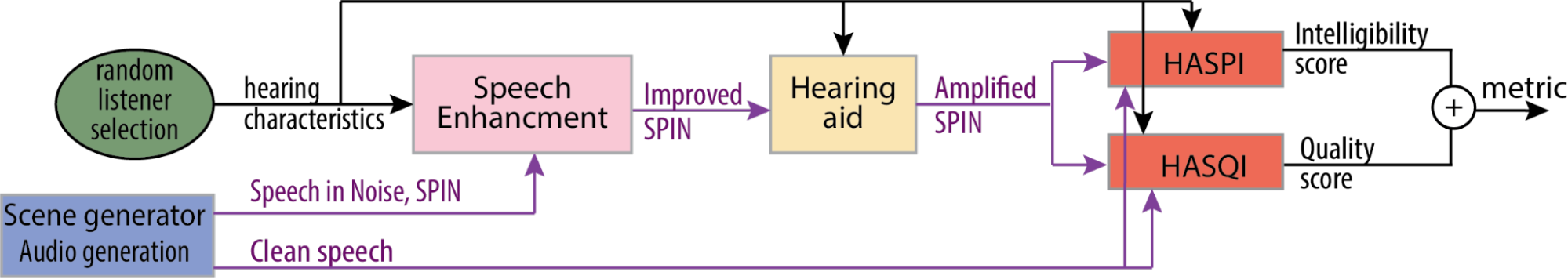
- A scene generator (blue box) creates speech in noise (SPIN).
- A listener is chosen (green ellipse), so the processing can be individualised for each listener with quantified hearing characteristics.
- The speech is enhanced (pink box). The entrants are tasked to improve this.
- The hearing aid we provide then amplifies the improved speech (yellow box)
- The amplified and improved speech that is emitted by your hearing aid is then passed to the prediction stage (red boxes). A combination of HASPI and HASQI is the output of the objective metrics for intelligibility and quality respectively (Kates and Arehart, 2021, Kates and Arehart 2014).
- All software tools will be available as a single GitHub repository. The software is split into core components e.g. HASPI, HASQI, and additional tools e.g. a hearing loss model. All software is open-source and in Python.
Room geometry
- Cuboid rooms with dimensions length by width by height .
- Length set using a uniform probability distribution random number generator with .
- Height set using a Gaussian distribution random number generator with a mean of 2.7 m and standard deviation of 0.8 m.
- Area set using a Gaussian distribution random number generator with mean 17.7 m and standard deviation of 5.5 m
Room materials
One of the walls of the room is randomly selected for the location of the door. The door can be at any position with the constraint of being at least 20 cm from the corner of the wall.
A window is placed on one of the other three walls. The window could be at any position of the wall but at 1.9 m height and at 0.4 m from any corner. The curtains are simulated to the side of the window. For larger rooms, a second window and curtains are simulated following a similar methodology.
A sofa is simulated at a random position as a layer on the wall and the floor. Finally, a rug is simulated at a random location on the floor.
The listener (receiver)
The listener has position,
This is positioned within the room using uniform probability distribution random number generators for the x and y coordinates (see Figure 2 for origin location). There are constraints to ensure that the receiver is not too close to the wall:
- either 1.2 m (sitting) or 1.6 m (standing).
Head rotation
The listener is initially oriented away from the target and will turn to be roughly facing the target talker around the time when the target speech starts
- Orientation of listener at start of the sample ~25° from facing the target (standard deviation = 5°), limited to +-2 standard deviations.
- Start of rotation is between -0.635 s to 0.865s (rectangular probability)
- The rotation lasts for 200 ms (standard deviation =10 ms)
- Orientation after rotation is 0-10° (random with rectangular probability distribution).
The target talker
The target talker has position
The target talker is positioned within the room using uniform probability distribution random number generators for the coordinates. Constraints ensure the target is not too close to the wall or receiver. It is set to have the same height as the receiver.
A speech directivity pattern is used, which is directed at the listener. The target speech starts between 1.0 and 1.5 seconds into the mixed sound files (rectangular probability distribution).
The interferers
The interferers have position
Each interferer is modelled as an omnidirectional point source. They will be radiating: speech, noise or music. They are placed within the room using uniform probability distribution random number generators for the coordinates. The following constraints ensure the interferer is not too close to the wall or listener. However, interferers are independently positioned with no constraint on their position relative to each other. They are set to be at the same height as the listener. Note, this means that the interferers can be at any angle relative to the listener.
The interferers are present over the whole mixed sound file.
Signal-to-noise ratio (SNR)
The SNR of the mixtures are engineered to achieve a suitable range of speech intelligibility values. A desired signal-to-noise ratio, SNR (dB), is chosen at random. This is generated with a uniform probability distribution between limits determined by pilot listening tests. The better ear SNR (BE_SNR) models the better ear effect in binaural listening. It is calculated for the reference channel (channel 1, which corresponds to the front microphone of the hearing aid). This value is used to scale all interferer channels. The procedure is described below.
For the reference channel,
- The segment of the summed interferers that overlaps with the target (without padding), , and the target (without padding), , are extracted
- Speech-weighted SNRs are calculated for each ear, SNR and SNR:
- Signals and are separately convolved with a speech-weighting filter, h (specified below).
- The rms is calculated for each convolved signal.
- SNR and SNR are calculated as the ratio of these rms values.
- The
BE_SNRis selected as the maximum of the two SNRs:BE_SNR= max(SNR and SNR).
Then per channel,
- The summed interferer signal, i, is scaled by the BE_SNR
-
BE_SNR
-
- Finally, i is scaled as follows:
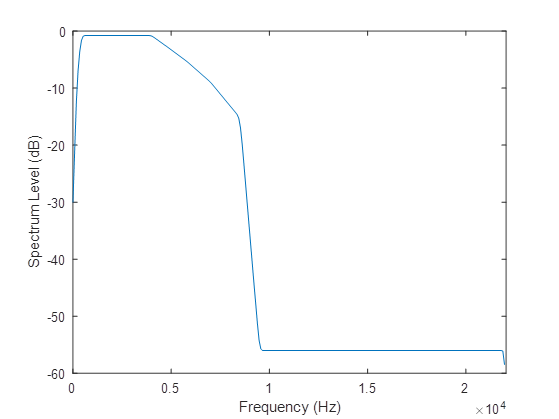
The speech-weighting filter is an FIR designed using the host window method [2, 3]. The frequency response is shown in Figure 2. The specification is:
- Frequency (Hz) =
[0, 150, 250, 350, 450, 4000, 4800, 5800, 7000, 8500, 9500, 22050] - Magnitude of transfer function at each frequency =
[0.0001, 0.0103, 0.0261, 0.0419, 0.0577, 0.0577, 0.046, 0.0343, 0.0226, 0.0110, 0.0001, 0.0001]
References
- Schröder, D. and Vorländer, M., 2011, January. RAVEN: A real-time framework for the auralization of interactive virtual environments. In Proceedings of Forum Acusticum 2011 (pp. 1541-1546). Denmark: Aalborg.
- Abed, A.H.M. and Cain, G.D., 1978. Low-pass digital filtering with the host windowing design technique. Radio and Electronic Engineer, 48(6), pp.293-300.
- Abed, A.E. and Cain, G., 1984. The host windowing technique for FIR digital filter design. IEEE transactions on acoustics, speech, and signal processing, 32(4), pp.683-694.